In industrial machine repair and installation, precision is everything. A tiny deviation of a micrometre can lead to thousands of Rands in downtime, lost production, or safety hazards. That is why calibration is vital. It guarantees that your equipment is not only properly adjusted but also officially recognised as compliant through formal documentation.
That documentation is your calibration certificate. It is a comprehensive record confirming that your equipment has been inspected, adjusted, and verified against recognised manufacturer standards. It serves as both your assurance of quality and the foundation of compliance, particularly in demanding sectors such as mining across Africa.
The question is whether you fully understand what the data in this record represents, and whether you are making the most of the quality in which you are investing.
Every Easy-Laser calibration carried out by Engineering Dynamics is accompanied by a formal report that captures the entire process. This includes:
- Traceability to international standards.
- Before and after readings for every adjustment, including laser power, inclinometer angles, detector alignment, and parallelism.
- The measurement uncertainty
- Environmental conditions.
Engineering Dynamics is among a select few centres worldwide accredited by the leading laser alignment OEM, Easy-Laser. Every two years, the Easy-Laser quality team re-certifies our technicians, ensuring that the expertise applied during calibration meets international standards. For years, African industries had to send vital measurement tools overseas, often waiting months and incurring high costs. With our accredited facility for Easy-Laser products in Pretoria, we have transformed that process.
Calibration at Engineering Dynamics is now faster, more consistent, and fully traceable. Typical turnaround is just one day, giving you a certified tool back in the field almost immediately and maximising operational uptime. Automation and careful monitoring reduce human error and ensure repeatable results, while every report documents the adjustments and measurements in full.
Here is a look at some of the key steps in the calibration process:
- Inspection and Cleaning
Every system is thoroughly cleaned and inspected for any physical damage that could impact its performance. Even a small mark on a laser head can lead to non-compliance, and this is noted in the report. - Laser Power Measurement
The laser output is measured with a calibrated optical power meter. It is then adjusted to the precise factory specification of 0.420 ± 0.02 mW. The certificate records the before-and-after values, allowing you to see the exact improvement. - Inclinometer Calibration
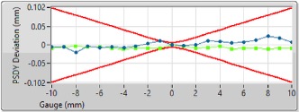
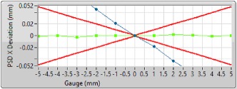
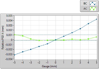
The inclinometer is tested at eight reference angles, spaced 45 degrees apart. . Graphs on the certificate show the inclinometer readings before and after calibration, together with the accepted limits.